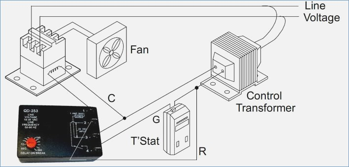
Icm Time Delay Relay Wiring Diagram
Download Icm Time Delay Relay Wiring Diagram Images. A 5v voltage regulator is used for giving 5v regular supply to the circuit. Select desired delay on make and.

To operating voltages and the number of output contacts ce.
Icm 102 dayton off delay timers. Multifunction multitime time relay wide time ranges many varieties acc. I finally decided to add another line to my charge controller and i wanted a steady power output instead the pwm that comes off of the dump controller so i a simple time delay circuit. Connect terminals in series with the starting device as shown in the wiring diagram below.
Belum ada Komentar untuk "Icm Time Delay Relay Wiring Diagram"
Posting Komentar