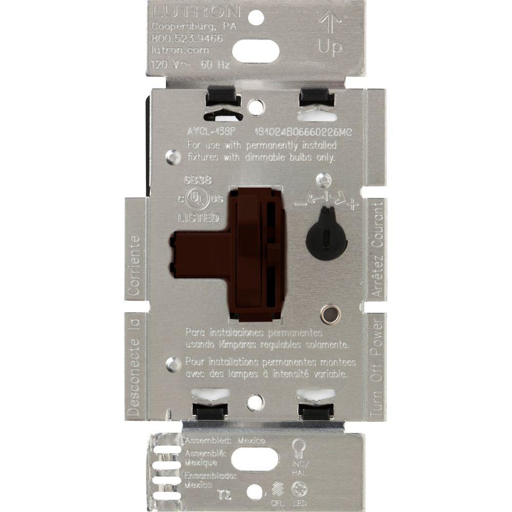
Low Voltage Dimmer Wiring Diagram
49+ Low Voltage Dimmer Wiring Diagram Background. The dimmers you find in your home are designed to operate from an ac voltage and use this ac because we now have to start with 12 v dc, we have to generate the ac voltage ourselves. Electronic low voltage (elv) dimmer wiring diagram.

0 10v dimming wiring diagram 0 10v dimmer switch leviton ip710 lfz or equal for other types of dimming control systems consult controls manufacturer for wiring instructions switched hot black switched hot red typical low voltage dimming wires purple gray typical electrical panel hot black.
0 10v dimming wiring diagram 0 10v dimmer switch leviton ip710 lfz or equal for other types of dimming control systems consult controls manufacturer for wiring instructions switched hot black switched hot red typical low voltage dimming wires purple gray typical electrical panel hot black. If so, can i still wire this dimmer switch in the same way as i had planned with an regular dimmer switch? Residential network cabling guide for your home including ethernet and coax. Electronic low voltage (elv) dimmers were originally designed to control electronic low voltage transformers used in low voltage (12v) mr16 type fixtures.
Belum ada Komentar untuk "Low Voltage Dimmer Wiring Diagram"
Posting Komentar